DC Motors
How they work, in 4 parts -- 12
November, 2001
|
|
|
|
|
|
|
|
High-speed output Back EMF Noise (ripple) on power lines Even without these avoidable factors, any electric motor will put noise on its power lines by virtue of the fact that its current draw is not constant throughout its motion. Going back to our example two-pole motor, its current draw will be a function of the angle between its rotor coil and field magnets:  Since most small DC motors have 3 coils, the coils' current curves will overlay each other:  Added together, this ideal motor's current will then look something like this:  Reality is a bit more complex than this, as even a high-quality motor will display a current transient at each commutation transition. Since each coil has inductance (by definition) and some capacitance, there will be a surge of current as the commutator's brushes first touch a coil's contact, and another as the brushes leave the contact (here, there's a slight spark as the coil's magnetic field collapses). As a good example, consider an oscilloscope trace of the current through a Mabuchi FF-030PN motor supplied with 2 V (1ms per horizontal division, 0.05 mA per vertical division): 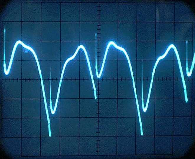 In this case, the peak-to-peak current ripple is approximately 0.29 mA, while the average motor current is just under 31 mA. So under these conditions, the motor puts about less than 1% of current ripple onto its power lines (and as you can see from the "clean" traces, it outputs essentially no high-frequency current noise). Note that since this is a 3-pole motor, and each coil is energized in both directions over the course of a rotor rotation, one revolution of the rotor will correspond to six of the above curves (here, 6 x 2.4 ms = 0.0144 sec, corresponding to a motor rotation rate of just under 4200 RPM). Motor power ripple can wreak havoc in Nv nets by destabilizing them inadvertently. Fortunately, this can be mitigated by putting a small capacitor across the motor's power lines (you'll only be able to filter out "spikey" transients this way, though -- you'll always see curves like the ones above being imposed on your power). On the flip side of this coin, motor power ripple can be put to good use -- as was shown above, ripple frequency can be used to measure motor speed, and its destabilizing tendencies can be used to reverse a motor without the need for discrete "back-up" sensors. To scope out what motor is best for a given BEAM
application, we'll need to do some math -- let's
move on to DC
motor performance
parameters. |
|
|
|
|
|
|
|
||
|
|
This page was last updated on |
|