DC Motors
How they work, in 4 parts -- 12
November, 2001
|
|
|
|
|
|
|
||||||||||||
|
Let's start by looking at a simple 2-pole DC electric motor (here red represents a magnet or winding with a "North" polarization, while green represents a magnet or winding with a "South" polarization).  Every DC motor has six basic parts -- axle, rotor (a.k.a., armature), stator, commutator, field magnet(s), and brushes. In most common DC motors (and all that BEAMers will see), the external magnetic field is produced by high-strength permanent magnets1. The stator is the stationary part of the motor -- this includes the motor casing, as well as two or more permanent magnet pole pieces. The rotor (together with the axle and attached commutator) rotate with respect to the stator. The rotor consists of windings (generally on a core), the windings being electrically connected to the commutator. The above diagram shows a common motor layout -- with the rotor inside the stator (field) magnets.
So since most small DC motors are of a three-pole design, let's tinker with the workings of one via an interactive animation (JavaScript required):
You'll notice a few things from this -- namely, one pole is fully energized at a time (but two others are "partially" energized). As each brush transitions from one commutator contact to the next, one coil's field will rapidly collapse, as the next coil's field will rapidly charge up (this occurs within a few microsecond). We'll see more about the effects of this later, but in the meantime you can see that this is a direct result of the coil windings' series wiring: 
The use of an iron core armature (as in the Mabuchi, above) is quite common, and has a number of advantages2. First off, the iron core provides a strong, rigid support for the windings -- a particularly important consideration for high-torque motors. The core also conducts heat away from the rotor windings, allowing the motor to be driven harder than might otherwise be the case. Iron core construction is also relatively inexpensive compared with other construction types. But iron core construction also has several disadvantages. The iron armature has a relatively high inertia which limits motor acceleration. This construction also results in high winding inductances which limit brush and commutator life. In small motors, an alternative design is often used which features a 'coreless' armature winding. This design depends upon the coil wire itself for structural integrity. As a result, the armature is hollow, and the permanent magnet can be mounted inside the rotor coil. Coreless DC motors have much lower armature inductance than iron-core motors of comparable size, extending brush and commutator life. 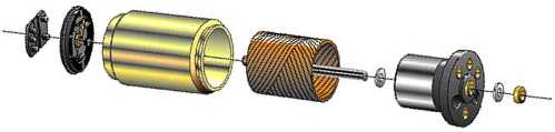 Diagram courtesy of MicroMo The coreless design also allows manufacturers to build smaller motors; meanwhile, due to the lack of iron in their rotors, coreless motors are somewhat prone to overheating. As a result, this design is generally used just in small, low-power motors. BEAMers will most often see coreless DC motors in the form of pager motors.
To get the best from DC motors in BEAMbots, we'll need to take a closer look at DC motor behaviors -- both obvious and not.
Notes: 1. Other (generally either very large, or fairly old) DC motors use windings to produce the external field as well. By using permanent magnets, modern DC motors are more efficient, have reduced internal heating, and use less power. 2. The following 3 paragraphs
borrow fairly liberally from material on a number
of pages of the MicroMo
web site. This is an excellent
site, and goes into much greater detail on the ins
and outs of coreless motor construction and
performance. Particular attention should be given
to their pages on Motor
Construction , and on
the Development
of Electromotive Force
. |
|
|
|
|
|
|
|
||
|
|
This page was last updated on |
|