|
|
The BEAM Circuits Collection is a BEAM Reference Library site.
"Chloroplast" solar engines
Craig Maynard's "baby" (and two
close relatives, courtesy of Wilf Rigter)
Craig Maynard dreamed up the Chloroplast solar engine (an interesting design, tho' it uses two parts you probably won't have sitting around in your parts drawer). Since I really can't describe it better than Craig can, here's his description (from the Chloroplast web site), followed up by commentary and a related circuit by Wilf Rigter:
Features:
- Maintains a minimum voltage of around 5 Volts, useful for maintaining digital logic or microprocessor circuits [actually, the minimum voltage can be either 3 or 5 volts, as a function of the parts you select -- ed.]
- Has a hysteresis from 5-7 Volts which is adjustable to suit the designer's needs. This "bonus voltage" is discharged across the motor, but discharging stops when the minimum threshold voltage (around 5V) is reached [again, minimum voltage is either 3 or 5 volts, maximum voltage is limited by your solar cell(s)-- ed.].
- Has more punch at a higher voltage than other solar engines, making it suitable for larger, "torquier" motors.
- Uses only two three-pin devices and two resistors available from most electronics retailers.
- Has no lock-up bugs.
- Very simple to free-form.
- Is very inexpensive.
- Extremely low quiescent current ( about 25 micro amps or less)
- Works the capacitor at closer to capacitor voltage limits for greater efficiency.
Theory of Operation:
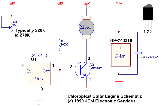
The heart of the Chloroplast is the Motorola MC34164-3 Micro power Undervoltage Sensing Circuit (U1 in the following diagram). In normal use, this component monitors the voltage at pin 2, and applies a ground at pin 1 ( out ) when the monitored voltage drops below 3V (34164-3 monitors 3 volts, 34164-5 monitors 5 volts). This low will then be used to assert a RESET on a microprocessor circuit. The output (an open collector) will be open when the output is above the threshold voltage.Through tinkering, I have discovered that placing a 220K to 270K resistor in series with the input of U1 will produce a significant hysteresis in this sensor's output. For instance, a 220K resistor as R2 will cause the output to ground until the solar voltage hits 6.8V, at that point it will open (float) until the solar voltage drops to 5.5V (a 1.3V hysteresis ). Different values of R2 will produce different results.
So how does this all work together? Well,
1.The solar panel will slowly charge up the storage capacitor C1 towards 6.8V. U1 will assert a ground (believing the voltage is too low) which keeps U2 (a high gain darlington NPN transistor) open and the motor OFF.2.When 6.8V is reached, U1 will open. The base of U2 will then be pulled high (through R1) and U2 will turn on, allowing the solar energy in the capacitor to discharge through the motor. The motor spins.
3.The motor will continue spinning and discharge the capacitor until the solar voltage falls to 5.5V.
4.At 5.5V, U1 will assert a ground at its output (Out), believing that the voltage is too low, and it must apply a RESET. This ground turns off U2 and the motor stops spinning and the system is ready for another cycle!
Here's the schematic:
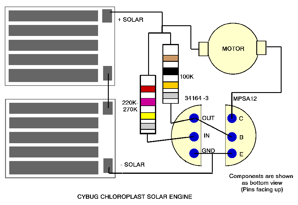
And if you want to free-form the circuit, here's how:

Wilf Rigter's take on the Chloroplast SE:
The MC34164 VS used in the Chloroplast SE is different in one respect from the 1381 VS (used in the VTSE and 1381 SEs) in that the MC34164 has an "open drain" output which requires a pull up resistor to the positive supply for the output to go positive.The CSE uses a resistor in series with the 34164 chip input and takes advantage of the fact that the quiescent supply current for the 34164 is higher when the output is low and decreases to almost zero when the output is high. That means the voltage drop across that series input resistor, generated by the quiescent 34164 current, must be added to the rated "turn on" voltage which raises the voltage on the supply cap required to turn on the 34164 (ie to 7V). After the 34164 turns on, the quiscent 34164 current drops to zero and the voltage drop across the series resistor also drops to zero, so that the voltage at the 34164 input pin suddenly jumps up to the supply cap voltage. The voltage at the "open" 34164 output pin is now pulled up to the supply through the output resistor, but the output pin voltage only rises to the forward voltage of the darlington transistor base emitter junction or about 1.2V. The darlington turns on and the collector supplies current to the rest of the circuit. The supply cap voltage starts to drop as the motor load etc depletes the cap charge until the supply voltage reaches the 34164 rated turn off voltage (ie 5V) and the process repeats
In one of my earlier MC34164 hysteresis SE designs (hySE), the 34164 upper threshold was raised by inserting a resistor in the ground lead and using the voltage drop generated from quiesent current and sinking the current from the output pull up resistor. Craig Maynard greatly improved on that design using the same principle but simplifying the circuit in his elegant Chloroplast design.
One popular misconception about these the Chloroplast SE is that it provides a convenient regulated 5V supply for powering up micros etc when in fact all it provides is a fluctuating supply voltage whose lower level can be set to 5V minimum. This is just a matter of design choice since all but the simplest latching or timed SEs offer this possibility.
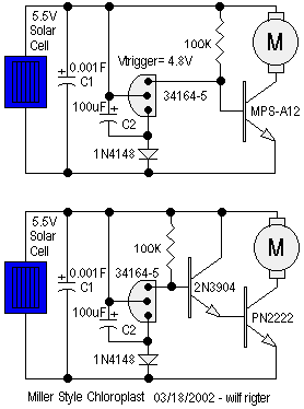
More recently, Wilf posted two Chloroplast-related SE designs ("Miller style" Chloroplasts) -- here are their schematics, and Wilf's description:

Here is a yet another hybrid SE, this time combining the principle of the Miller Engine with the Chloroplast SE. Two versions are shown with the top one using a Darlington transistor and the bottom using 2 separate NPN transistors which have a lower "on" voltage and deliver slightly more power to the motor. Both MS Chloroplast SE trigger at 4.8V and reset after a time determined by C2. The value of the main storage cap C1 can be 10,000uF to 1F and the value of timing C2 can be 1uF to 100uF.This SE design can also be used with the 3V MC34164-3 chip, 3.4V solar cells and 2.5V super caps for a lower voltage applications (2.8V).
My prototype of the lower schematic sits in the window near the 49th parallel and with C1=10,000uF and C2=100uF, the trigger point is 4.8V and the cycle time was about 20 sec with yesterday's overcast sky and about 2.5 seconds in this morning's glorious sunshine. The efficient mightymo gearmotor turns about 4 rotations in 1 second.
|
|
|
|
|
|
||
|
|
This page was last updated on |
|
