|
|
|
|
The BEAM Circuits Collection is a BEAM Reference Library site.
Mazibug solar engines
An SE derived from a
photopopper
As part of a thread of discussion on the Mazibug photopopper design, Wilf Rigter wrote up this description of the SE portion of the Mazibug 3 circuit:
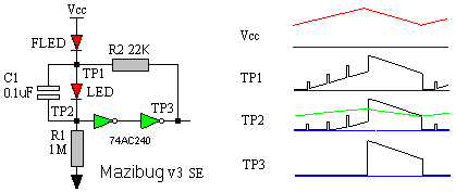
The Mazibug SE works much like a FRED SE; the waveforms should help you get the picture. Assume TP1-TP3 are at 0V (the blue line in the waveforms) to start and Vcc is just rising above the voltage where the FLED starts to conduct. The voltage at TP1 is generated by the current passing through R2 which is grounded at TP3. As Vcc rises, the FLED starts to pulse and every pulse causes a voltage spike across R3. That voltage spike is coupled through C1 to TP2. As Vcc continues up, the LED turns on and the DC voltage on TP2 starts to ramp up. The pulses from TP1, superimposed on the DC voltage of TP2, are used to "sample" the Vcc level and at some point (~4V) the pulsed voltage on TP2 crosses the 74AC240 threshold shown in the TP2 waveform with the green line.When the 74AC240 is triggered, TP3 goes to Vcc and R2 bypasses the FLED. TP1 also rises to Vcc and TP2 rises to Vcc -1.3V=2.7V which is Vcc minus the voltage drop across the LED. As Vcc drops to the reset level (2.6V) , the voltage at TP2 crosses the 240 threshold level again and TP3 goes to ground. Keep in mind that the 74AC240 threshold is about Vcc/2. The 74HC, HCT, ACT types have lower thresholds and may require some adjustment.
The value of R1 can be 100K-1M and the value of R2 is between 5.1K-33K. For testing use a 1000 ohm current limited 6V battery supply to simulate the solar cell and a 3,300 uF cap for storage. Measure the voltage on the cap with a voltmeter to determine the trigger and reset levels. I used a NPN transistor and a small motor for a load for these tests. Remember, like the FRED design, the FLED is sensitive to light and should be shielded. FLED SEs always require some fiddling to get them going but they do use commonly available parts. Of course a 1381 Mazibug would be much more predictable / reliable.
|
|
|
|
|
|
||
|
|
This page was last updated on |
|