|
BEAM From the Ground Up is a
BEAM
Reference Library
site.
|
|
"Hacking" a Mac floppy disk eject
motor
From start to finish
|
A fair number of BEAMbots use a surplus
Macintosh computer floppy eject motor (in
particular, the eject motor from Sony-manufactured
Mac floppy drives) as a gear motor.
These motors have a lot going for them -- they
are strong, efficient,
and (at least for the time being) easily available
at swap meets and on auction sites for just a few
dollars. The purpose of this tutorial is to show
you how, starting with a surplus floppy drive, to
yield a motor ready for installation in your
robot.
|
|
|
|
Step 1: Get a floppy drive, and
"uncase" it
|
First off, you need to find a floppy
drive for an Apple
Macintosh computer (you can still find
these, although they'll be getting scarce
soon since floppy drives are no longer
being made).
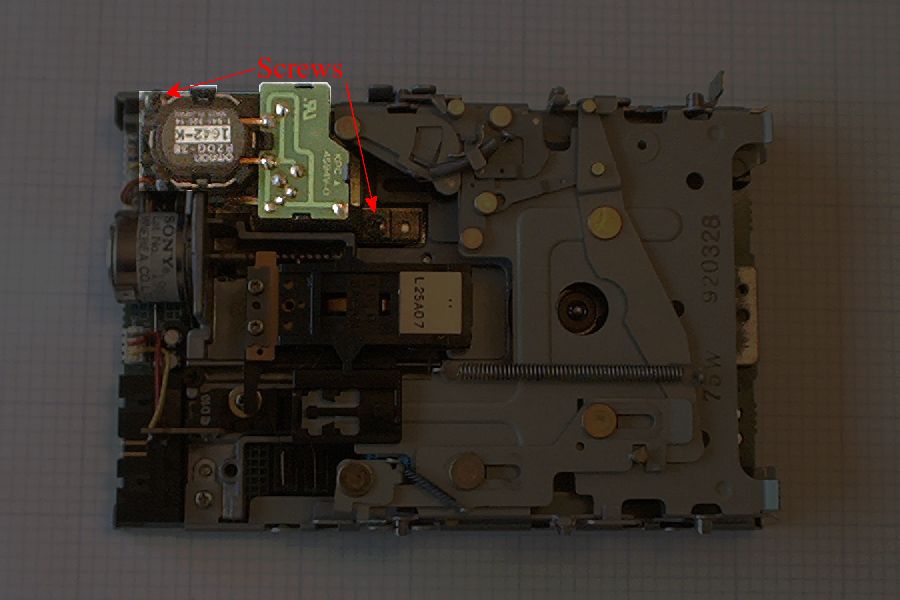
Mac floppy drives start out in a
4-sided case. You'll need to unscrew 4
Phillips-head screws (2 on each "edge" of
the case), then pry the drive guts out of
the sheet-metal case. I have yet to find a
use for the casing, so I just throw it
away.
This picture shows the "interesting"
face of a cased floppy drive; the eject
motor is on the back face of the circuit
board.
|
|
|
|
|
Step 2: Remove the motor from
the drive
|
Flip the internals over, and you should
see something like this image.
I've attempted to highlight the motor;
I've also shown the two Phillips-head
screws that hold the eject motor in place.
Remove these screws and wiggle the motor
free.
|
|
|
|
|
|
|
|
Now take a small flat-blade
screwdriver, and pry the motor's plug free
from the jack. If you do this carefully,
you can reuse this jack on your 'bot.
Your motor is now ready for your
attentions. Don't throw the rest of the
drive away -- there's plenty more you can
use (tho' of course, it's not the subject
of this tutorial).
|
|
|
|
|
|
|
|
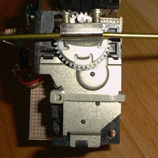
You'll find one of two types of motors
in these drives -- note that the
differences are subtle, both types have
the same Omron model number (R2DG-38), and
they're about 95% identical.
The biggest difference between the two
is that one type has a metal plate on the
face of the output gear, while another
does not. Let's call these two motor types
the "metal" and "plastic"
versions, for short (we'll be referring to
these types, and some other subtle
differences that go along with them,
later).
When you work on one of these motors,
it'll most likely be a plastic
version; they seem to be more common, and
I suspect they're a more-recent
version.
|
|
|
|
|
Step 3: Motor electrical
rework
|
Here's your freed motor. Carefully
wriggle the little 3-wire harness out of
the clips that hold it next to the
motor.
You'll need to undo the latch and
(patiently) pry up the little circuit
board. This requires a bit of care as
things are pretty stiff to start, but once
you get past a certain point, the board
suddenly just comes free.
|
|
|
|
|
|
|
|
Here's what the underside of the
circuit board looks like. You need to
remove the limit switch and resistor(s).
Here's where metal vs. plastic
bit comes in again -- the metal
variants have two resistors here, the
plastic ones have just one.
The resistor(s) is there for the
motor's original use -- it allows the
motor to stop precisely and reliably when
power is removed from the motor. We don't
need this, and besides, the resistor(s)
waste a lot of power while the motor's
running.
I desolder the resistor(s), then clip
the limit switch off with cutters.
It's good practice (i.e., cheap
insurance) to install a filter capacitor
across the motor's power leads. You can
put this right where the resistor was (so
it's a good idea to desolder this
component).
These motors put very little ripple on
their power lines; accordingly, you don't
need much of a capacitor to filter it -- I
generally use 0.22 uF -- but it must be a
non-polarized cap.
|
|
|
|
|
|
|
|
I sometimes also remove the "stock"
wires, and solder on my own leads directly
to the two motor terminals (this gives me
longer leads, and allows me to use the
original motor leads & plug elsewhere
in my projects). If you choose not to do
this last step, you can use two of the
three wires the motor comes with. Clip off
the yellow wire (or just don't connect
anything to it), and use the brown and red
leads as follows:
For CCW rotation (facing the
white output gear, with the metal "nub"
pointing at you), connect the red wire
to positive voltage, and brown to
negative (or ground).
For CW rotation, just reverse this
polarity.
At any rate, gently push the circuit
board back into place (it'll snap in), and
give the exposed solder joints a thick
coating of "Plasti-Dip" (a piece of
electrical tape will also work) so the
joints can't short anything out when you
put it on your 'bot.
Note that here's another difference
between the plastic and
metal models -- in a metal
one, the motor is connected to its circuit
card via black and red wires; in a
plastic one, the motor is connected
via thin copper strips
|
|
Two connection methods; on
the left, with new wires; on the right,
with the original brown and red
wires.
|
|
|
Step 4: Motor case
trimming
|
I always cut off the crosshatched
pieces in this drawing -- it makes the
motor a bit smaller, and less cumbersome
(so it's easier to mount on a 'bot). I do
this with a band saw (I also tinker in
woodworking, so I already have one); if
you don't have a band saw, a hacksaw and
file will do.
|
|
|
|
|
Step 5: Providing for
attachments and (maybe) a centering
spring
If you're building a 2-motor walker, one motor
will definitely need a centering spring; the other
probably won't (so long as its rotational axis
provides "lift" for the 'bot). Just to be safe,
I'll cover both. Meanwhile, you may be using this
motor on a head, so I'll cover that as well.
|
If you're using this motor in a walker,
you'll need some way to attach legs to it.
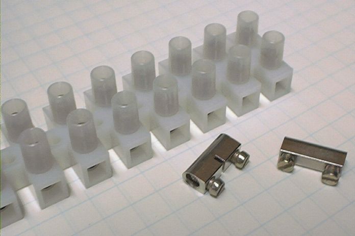
I use the cores from "European-Style
Junction Strips."
These allow you to attach two separate
legs to one motor, which gives you lots of
flexibility in leg design. They also
attach to motors easily with epoxy.
|
|
|
|
|
|
|
|
On a 2-motor walker, at least one of
your motors will need centering springs.
To give these attachment points, I use
"split ring" washers (modified, of
course). I put them in a vise (stout
pliers would work too), then bend the ends
of the split in opposite directions to
give the surviving part of the washer
"feet." I've got unmodified and modified
washers in the image at right.
You'll need 2 of these modified washers
for each motor that'll get a centering
spring.
|
|
|
|
|
|
|
|
I use different mounting hardware if
the motor is destined for a head
-- a flathead machine screw, washer, and
nut (the washer's there primarily to give
you more metal surface to epoxy to).
This allows you to attach the motor
shaft to a base by just using washers and
two nuts on the screw's shaft. For this
particular use, a plastic-face
drive motor is easier to work with, since
you'll have to remove the "nub" from the
gear face in order to epoxy the screw to
it.
|
|
|
|
|
|
|
|
Now prep your parts for gluing -- the
surfaces you want the epoxy to "grab" need
to be roughened a bit (via sandpaper),
cleaned, and degreased. For degreasing, I
use rubbing alcohol on a clean rag.
|
|
|
|
|
|
|
|
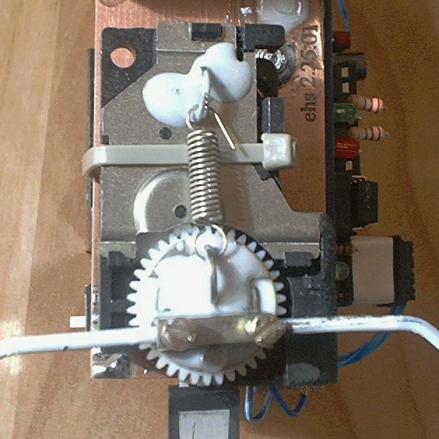
Now just glue your parts together. For
what it's worth, I use a type of epoxy
made primarily for metal bonding for this
work. It seems to work a bit better,
doesn't cost much more, and is as easily
available as the regular stuff.
When you're done, your final result
(for a walker motor with centering spring)
will look something like this.
|
|
|
|
|
Step 6: Mounting the
motor
These motors have a lot of odd, lumpy
protrusions on all sides, so they can be
challenging to mount to a 'bot. I've found a
method, though, that works for me -- using a
rubber, self-adhesive "bumper" (the thin, flat,
disk-shaped ones, not the round "bumps") and cable
ties.
|
This step is easy; just put one of your
self-adhesive bumpers on the motor's
circuit card.
|
|
|
|
|
|
|
|
You now have a relatively flat surface
on the back of the motor (plus you've got
a resilient mounting point in the form of
your rubber "bumper"). Just use a small
cable tie to hold the motor in place.
As you tighten the cable tie, the
rubber "bumper" will compress, and the
motor will twist a bit until it is in a
flat position.
|
|
Here are two examples of
motors mounted using this
method.
|
|
|
For more
information...
|
|
Details on the performance specs of this motor are
available here.
|
|