|
|
|
|
The BEAM Circuits Collection is a BEAM Reference Library site.
The T3SE type 3 solar engine
Wilf Rigter's take on a type 3
solar engine (circuit diagram and text © Wilf
Rigter)
The all-transistor T3SE works much like a conventional SE: like the Tritium, it fires when the charging current drops below the minimum and after the circuit triggers, positive feedback is used to latch the circuit, resetting at a fixed voltage on the main cap.
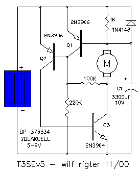
How the T3SE works:
When the cap is discharged, the solar cell starts to
charge the main cap mostly through the base - emitter
junction of Q1 and some current passing through the 1K
resistor with a maximum forward voltage drop of .6V. This
causes the collector of Q1 to be saturated and the voltage
on the collector will be close to the Q1 emitter voltage.
This clamps the base emitter junction of Q2 and cuts off the
Q2 collector current which would otherwise flow into the
base of Q3.
When the voltage across the 1K resistor drops below .6V (i.e., 1 KOhms x 0.6 mA), Q1 comes out of saturation and "unclamps" the Q2 base. This allows Q2 to turn on with base current supplied through the 220 K resistor. When Q2 turns on, it supplies base current to Q3 and the load (here a motor) is picked up.
There are two positive feedback paths:
- When Q2 turns on, the voltage on the Q2 and Q1
emitters drops to about 2.5V and rapidly turns off
Q1.
- The Q2 emitter collector current passes to the base of Q3 with most current supplied the solar cell and some through R1.
The Q3 base emitter voltage drop sets the reset voltage and also stops the solar cell from charging C1 during the discharge which would otherwise cause the T3SE to turn off again. When Q3 turns on, the Q3 collector supplies motor current but also additional Q2 base current through the 100K resistor. The double positive feedback makes the T3SE switch on rapidly with little wasted voltage drop on Q3.
When the voltage on the cap drops below about 2.6V, Q2 turns off and the positive feedback will cause the SE to quickly reset.
Leaving the 1K resistor out (i.e., setting its value to infinity) changes the T3SE behaviour. As long as the solar cell is generating a higher voltage than the capacitor voltage, the SE won't fire. Wave your hand in front of the solar cell and it fires. In fact, without the 1K resistor, the T3SE makes an excellent D1-type SE.
|
|
|||
|
|
|
|
|
|
Storage capacitor |
|
|
|
|
Solar cell |
|
|
|
|
1 KOhm resistor |
|
|
|
|
100 KOhm resistor |
|
|
|
|
220 KOhm resistor |
|
|
|
|
1N4148 diode |
|
|
|
|
2N3904 transistor |
|
|
|
|
2 x 2N3906 transistor |
|
|
|
|
|
||
|
|
This page was last updated on |
|