|
|
|
|
The BEAM Circuits Collection is a BEAM Reference Library site.
Wilf Rigter's SIMD1 V1
Part of a family of nocturnal
solar engines (all circuits on this page ©
Wilf
Rigter ; note that the majority
of this explanatory text comes from either postings by, or
correspondence with Wilf)
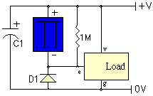
SIMD1 V1 is functionally the same circuit as SIMD1 V0 but provides an active high signal to the load when night (or at least darkness) has arrived.
 |
 |
|
|
e = enable (active high); v = Vcc; g = Gnd |
LED load with gate driving enable |
As with the SIMD1 V0, a 100K - 1M resistor across the solar cell helps with turnoff, but the SIMD1 V1 requires almost complete darkness before switching.
|
|
|||
|
|
|
|
|
|
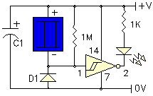
Storage capacitor |
|
|
|
|
Solar cell |
|
|
|
|
Germanium diode |
|
|
|
|
1 MOhm resistor |
|
|
|
In the example circuit, the SIMD1 V1 is again shown driving a single LED. This example (as with the V0 example) makes use of a 74*14 Schmitt inverter to switch power on within the load.
Normally the active high output from the inverter is used to enable the remainder of the CMOS gates which then perform some useful function. When the SIMD1 triggers at night, it snaps on and the output signal can be used to control the 5 remaining 74HC14 inverters connected in parallel with the outputs used as a "power" switch. Or the signal can be used as the tristate control of a 74HC240 or 74HC245 or be used as a PNC input for an Nv net etc. to apply the stored energy to the load.
A point to remember when adding on the rest of the circuit is that CMOS logic draws considerable supply leakage current when inputs are not at 0V or Vcc. That problem virtually disappears when Vcc <3V; as a result, this circuit is only useful with a single 2.5V capacitor and a lower voltage solar cell. Also note that the example circuit also has a somewhat high switching voltage when the difference between the solar cell voltage and the capacitor voltage is sufficient to turn on the CMOS gate. A 74HC14 switches at a difference voltage of 2/3 Vcc. In general, HC logic switches at 1/2 Vcc and HCT logic around 1.8V.
|
|
|
|
||
|
|
This page was last updated on |
|