Circuits Logo

> Home

V Motor drivers

 > About H-bridges

 > 6-trans. Tilden H-bridge

 > "Full-featured" H-bridge

 > Wilf's reversing H-bridge

 > Buffered H-bridges

 > Bolt's 4-trans. H-bridge

 > The Z-bridge

 > 74*245-based driver

 > 74*240-based driver

 > 74*24x drives compared

 V Stepper motor drivers

  > Wilf's NuStepper

  > Solarbotics' Nv

  > BEAM Stepper

> Solar engines

> Sensors

> Complete robots

> Misc. circuits


The BEAM Circuits Collection is a BEAM Reference Library site.

Wilf's Nu-based stepper motor drive circuit
The NuStepper


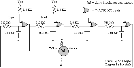
Wilf Rigter came up with a nifty (single-IC!) circuit to drive the bipolar stepper motor that's a part of floppy drives:
TBR

I've reproduced Wilf's own description of this circuit from here:


Subject:Nu circuits 101- the NuSTEPPER

Date:Mon, 18 Jan 1999 19:48:25 -0800

From:Wilf Rigter

If you like (or don't like) Nv Microcore s, you will love the NuRING.

The NuCore was described in my earlier post and has now been renamed as the NuRING. Like the Nv Microcore , the NuRING is made from a number (ie 4) of process nodes connected in a ring. It uses a single capacitor and resistor with a gain stage for each node but as an integrator instead of a differentiator. Think of it as a "relaxed" neuron!

While there are similarities in function between the Nv Microcore and the NuRING, there are some important differences.

First of all, any linear devices like AC240 or AC245 work well as gain elements for (>1Nu) NuRING circuits. As long as the sign of all inversions in the NuRING is negative, it can made from any combination of inverting or noninverting elements. The process pattern in linear NuRINGs is just as robust as the Schmitt trigger NuRINGS and the voltage swing at the Nu bias point of NuRINGS >2Nu approaches rail to rail.

I had previously used the Nv Microcore circuit to generate a "wave" step sequence for unipolar and bipolar type stepper motor s and I realized that the NuRING Grey Code "phase" and "phase to phase" output patterns were identical to 1/2 step sequences for both types of stepper motors.

I tested this idea with a small bipolar stepper motor of the type used for head posistioning in a 3.5 inch FD. In order to use Nv Core circuits to drive stepper s, you must use output buffering for feedback isolation because the Nv neuron is sensitive to motor transients which in large quantlties could cause process modulation, instability and saturation if motor windings were connected directly to a Nv Core.

However the Nu offers exquisite noise imunity and NuRING outputs can be directly connected to stepper motor s since any motor transients are integrated at the bias point.

In fact, I have designed this elegant 4NuRING reversing stepper circuit (I believe it's unique!) using a single 74AC86 as shown [above].

When either REV or FWD is low the stepper rotates in that direction. With the component R=510K and C=0.01 [mF, ed.] the speed is 4 revolutions per second and power consumption 40 mA. When both inputs are high or low the stepper is stopped and the current is zero. While torque is quite low it's useful for the lead screw application of the FD stepper motor.

I hope you will agree that this NuSTEPPER design is surprisingly simple with very high functionality in the best BEAM tradition.

Note that the NuCore posting that Wilf refers to is archived here, while the original (with ASCII art) NuRing posting reproduced above is archived here.

I'll be updating this page as I (get time to...) experiment with Wilf's circuit over the coming months.

ImageWarning -- circuit under development; material that follows may not be fully accurate!

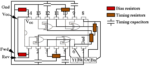
Here's a different layout of the NuStepper circuit diagram, with traces and other components overlaid on the 74AC86 chip diagram:
Image

The four boxes in the lower right corner (Yl / Bk / Or / Bn) represent the pins on the stepper motor plug, and the corresponding colors of the stepper motor's wires.

Here's the life-size PCB "artwork" for Wilf's NuStepper. A higher-res (x8) version is available here.

NuStepper PCB life-size diagram

Coming soon -- pictures of a populated NuStepper PCB!


Creative Commons License
This work is licensed under a
Creative Commons License.

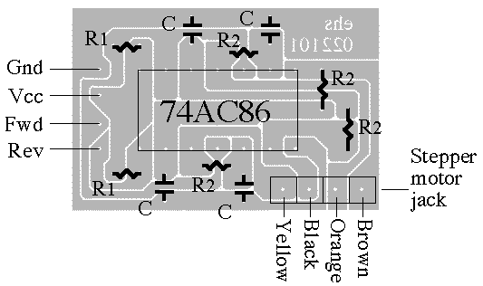
Here's how to lay out the components on a NuStepper PCB (this image is 4 times the size of the actual PCB since this is a fairly small board):
NuStepper PCB component layout

 Parts list

Part ID

# required

Description

R1

2

Input ("bias") resistors; 510 KOhm nominally

R2

4

Timing resistors

C

4

Timing capacitors

J

1

Stepper motor jack (salvaged from the same floppy drive that the motor came from)

74AC86

1

Quad XOR IC

The values for C and R2 determine the neuron firing times

When I build up this card, the 74*86 IC is "socketed," both to protect the IC during soldering, and to allow for experimentation with IC subfamily. Similarly, the timing resistors and timing capacitors are plugged into individual sockets to allow for tinkering with circuit timing (i.e., motor rotation speed).


Sitemap  Image  Search  Image  Legalities  Image 
Page authors: Wilf Rigter, Eric Seale
This page was last updated on

Creative Commons License
This work is licensed under a
Creative Commons License.