|
|
BEAM From the Ground Up is a BEAM Reference Library site.
Bicores
What to do with 2 Nv
neurons
Many BEAMbots are based on bicores (2-Nv neuron "loops") in some fashion or another (and there are two main kinds of bicores -- but more on that later). Even if you're not building a bicore-based BEAMbot, studying how bicores work will help you understand more-complex Nv networks. So how do we get there from here?
The grounded bicore
Let's start with two Nv
neurons in a row:

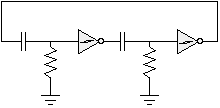
Now hook the output of the second neuron to the input of the first:

This is a basic, "vanilla" bicore. Since both neurons' resistors are connected to ground, it's official full name is the grounded bicore. Thanks to the two inverters, this bicore will happily oscillate (the outputs of the two inverters will always be opposite each other) without further input.
The frequency of oscillation is a function of the values you chose for the resistors and capacitors -- higher values result in slower oscillation frequency. The time that any given Nv neuron is "active" is very nearly equal to R*C (in seconds). "Typical" values for these are 0.1 - 0.33 uF for the capacitors, and 1-4 MOhm for the resistors (so with 0.1 uF capacitors and 1 MOhm resistors, each Nv neuron "fires" for about 0.1 second). Depending on your application, and what's being driven by the bicore, you may want something faster or slower than this.
You'll generally use Schmitt inverters for building grounded bicores -- so these circuits will most-often be built up from 74*14 or 40106 ICs. A Schmitt inverter has built-in hysteresis circuitry -- so, the rising input voltage at which its output toggles "down" is guaranteed to be higher than the falling input voltage at which its output toggles "up." With a slow-rising or slow-falling input in a noisy environment (which describes a grounded bicore's job precisely), a conventional inverter could start to toggle on and off as the input approaches the threshold -- while a Schmitt inverter is guaranteed to toggle very cleanly.
The suspended
bicore
All this is well and good, but there's experimenting to be
done! Let's start tinkering with our grounded
bicore:

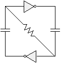
We can simplify this circuit a bit, and make it more symmetric by connecting the inverter inputs together with a single resistor (thus making it a suspended bicore):
 ... or ...
Note that we've gotten rid of one resistor, without really changing much in the way of circuit functionality.
Courtesy of Wilf Rigter, here's an animation of a suspended bicore in action:
|
|
|
Note that a Schmitt inverter's hysteresis circuitry is helpful in most Nv circuits, but potentially fatal for suspended bicores. Since the two inverters' inputs are directly connected by a resistor, there will come a point where their input voltages are the same (namely, Vcc / 2). If Schmitt inverters were used, the suspended bicore would come to a screaching halt -- since the inverters' hysteresis logic would prevent a transition through Vcc / 2. There is, though, a trick to get around this if you absolutely have to use Schmitt inverters in a suspended bicore. If you don't have a 74*240 inverter handy, you can still use the 40106 / 74*14 but instead of using 2 identical capacitors, one capacitor will need to have at least 2 times the capacitance of the other (i.e., 2 or 3 caps in parallel, or a 0.22 uF vs 0.1 uF cap). This will, of course, lead to asymmetrical timing (one neuron will be active for 2 or 3 times longer than the other) -- which may or may not be a problem depending on your application. |
A common way to modulate the duty cycle in a suspended bicore uses a pair of photodiodes across the timing resistor. If more light falls on one diode compared to the other, the duty cycle of the bicore output signal will change (e.g., 1:2 ratio). Now the motor will rotate twice as long in one direction than the other. It's a bit like taking one step back and two steps forward, on average you go forward.
|
|
|
Wouter Brok has written an Analysis of the Suspended Bicore, and Experiments with the Suspended Bicore. Wilf Rigter has an excellent, advanced treatment of Nv neurons, and Nv networks in his paper "Nervous Neurons -- Process and Transitions." As for implementation, Ian Bernstein has a
tutorial on free-forming
a bicore here. |
|
|
||
|
|
This page was last updated on |
|

 In
this diagram, red denotes Vcc and blue is 0 Volts;
the colors in between indicate various levels
between 0 Volts and Vcc. Yellow color at the input
of the