|
|
|
|
BEAM From the Ground Up is a BEAM Reference Library site.
Single-junction semiconductor
devices
Diiiiioooooddes! Get yer' red-hot
diiiiioooooodddes!
As was mentioned elsewhere, a P-N junction is the boundary between a piece of P-type and a piece of N-type semiconductor material. Russell Ohl and his colleagues discovered the unique properties of such a boundary, first and foremost that that a P-N junction makes an effective diode.
This page is devoted to the discussion of all semiconductor devices with just a single P-N junction, namely:
- Diodes in all their flavors, including
- Silicon and germanium diodes
- Zener diodes
- Light-emitting diodes (a.k.a., LEDs) -- both
regular & flashing
varieties
- Photodiodes
- Silicon and germanium diodes
- Solar cells (which are essentially just really big photodiodes)
Diodes
Diodes are components that allow current to flow in only one direction (up to a point, but more on that later), due in part to the fact that they only have a single P-N junction.Like many components, diodes have a positive side or leg (a.k.a, their anode), and a negative side (cathode). When the voltage on the anode is higher than on the cathode then current flows through the diode (the resistance is very low). When the voltage is lower on the anode than on the cathode then the current does not flow (the resistance is very high).
An easy way to remember this is to look at the symbol for a diode -- the "arrow" in the diode symbol points the direction in which it allows current (hole flow) to flow.
The cathode of a diode is generally marked with a line next to it (on the diode body). You can see a similar line in the schematic symbols, above.
Diodes are also some times marked with an identifying color code (similar, but not identical, to that used for resistors); a good explanation is given here.
Note that when current is flowing through a diode, the voltage on the positive leg is higher than on the negative leg (this is often referred to as the diode's "forward voltage drop"). The magnitude of the voltage drop is a function of (among other things) the semiconductor material that the diode is made from.
Silicon diodes (for example, the 1N914 and 1N4001)are the most common and cheapest, and have a forward voltage drop of about 0.65 volts. Germanium diodes (for example, the 1N34A) have a forward voltage drop of about 0.1 volt. Germanium diodes, though, are typically much more expensive than silicon diodes; luckily, they're salvageable from lots of circuit boards. To test whether or not a diode is Germanium, get out your multimeter, put it on diode test, and measure the diode's forward voltage drop directly. A Germanium diode will read less than 0.3, a Silicon will read above 0.5.
You can avoid voltage drop entirely in some cases by using a transistor instead of a diode -- see Wilf Rigter's article here.
Zener diodes
The Zener diode is designed to have a specific reverse breakdown voltage (i.e., conduction voltage when reverse-biased). Because of this, Zener diodes can be used by themselves as voltage-sensitive switches, or in series with a current-limiting resistor to provide voltage regulation.Photodiodes
All P-N junctions are light sensitive; photodiodes are just P-N junctions that are designed to optimize this effect. Photodiodes can be used two ways -- in a photovoltaic (here it becomes a current source when illuminated -- see solar cell), or photoconductive role.To use a photodiode in its photoconductive mode, the photodiode is reverse-biased; the photodiode will then allow a current to flow when it is illuminated.
ThermoCentrovision has an interesting site on the technology behind photodiodes here.
Light-Emitting Diodes (LEDs)
All diodes emit some light when forward-biased. LEDs are made from a special semiconductor (like gallium arsenide phosphide) which optimizes this light output. Unlike light bulbs, LEDs rarely burn out unless their current limit is passed. A current of 0.02 Amps (20 mA) to 0.04 Amps (40 mA) is a good range for LEDs (never go past 50 mA). LEDs have a forward voltage drop of about 1.6 V.LEDs have a cathode and an anode just like regular diodes. To determine an LED's polarity, you can do one of three things:
- Look for a line in the metal inside the LED (it may be difficult to see). This line is closest to the anode of the LED.
- Find a flat spot on the edge of the LED -- this flat spot is on the cathode.
- The anode of an LED is generally longer (at least, when it's a new, non-salvaged, LED).
When current is flowing through an LED the voltage on the positive leg is about 1.4 volts higher than the voltage on the negative side (this varies with LED type -- infrared LEDs have a lower forward voltage requirement, others may need up to 1.8 V). Remember that there is very little resistance to limit the current, so a resistor must be used in series with the LED to avoid destroying it (note, though, that some panel-mount LEDs come from the factory with a current-limiting resistor soldered to them).
Also note that LEDs can be used as photodiodes (tho' their sensitivity is relatively low, so they're only useable this way in very bright conditions).
Flashing LEDs (FLEDs)
A flashing LED is just an LED with a built-in microcircuit to cause it to flash periodically. Since the FLED draws current when it flashes, we can use FLEDs to drive a number of timing-dependent circuits (via the fact that it periodically becomes conductive). In particular, see the discussion of the FLED solarengine design. Like other LEDs, FLEDs are light-sensitive, and so flash faster in brighter light. Note that some FLEDs need 3 V minimum to work in, but FLEDs don't in general require current-limiting resistors (at least, I've never seen one that does).
BEAM Usage
I have a writeup on diode usage in BEAMbots here.
Solar cells 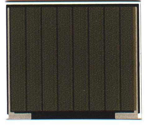 (image courtesy of Solarbotics
)
(image courtesy of Solarbotics
)
Solar cells are basically just P-N junction photodiodes with a very large light-sensitive area.Note that any solar cell is characterized by a maximum Open Circuit Voltage (Voc) at zero output current and a Short Circuit Current (Isc) at zero output voltage. Since power can be computed via this equation:
P = I * V Then with one term at zero these conditions (V = Voc / I = 0, V = 0 / I = Isc) also represent zero power. As you might then expect, a combination of less than maximum current and voltage can be found that maximizes the power produced. Many BEAM designs (and, in particular, solar engines) attempt to stay at (or near) this point. The tricky part is building a design that can find the maximum power point regardless of lighting conditions.
BEAM Usage
I have a writeup on solar cell usage in BEAMbots here.
|
|
|
SatCure has a tutorial page on diodes here. Iguana labs has a tutorial on using LEDs here. For true LED fanatics, there's now even an online "LED Museum" For an amazing amount of information on solar cells and solar energy, check out the U.S. Dept. of Energy website on photovoltaic technology. For an illuminating comparison of the various photo-sensitive devices, make sure to check out "Choosing the Detector for your Unique Light Sensing Application." |
|
|
||
|
|
This page was last updated on |
|