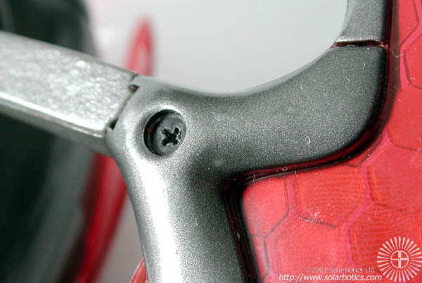

The limb attachments all follow the same formula of a slot / tab insertion, secured by a single phillips-head screw. Removal of the screw is easy enough, but attempts to jimmy it free from the leg itself proves difficult. I suspect that there's an adhesive at work here...

The rear limb is mounted in a similar manner to the front legs. You'll note the small rubber nubs on the contact points on both the front and rear legs for traction on smooth surfaces.
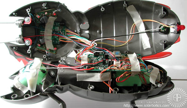
Let's crack this sucker open! OK, after removing the 6 screws on the bottom of the B.I.O. Bug, we can separate the shell halves.
The bottom half has most of the components, with the top half housing 3 circuit boards; 2 for the eyes, and 1 for the forehead. There is a ribbon cable tying these head circuits to the CPU on the main PCB in the bottom half of the B.I.O. Bug. The top half also contains the piezo transducer that the B.I.O. Bug uses to generate its noises (it's the little black circle in the very back of the top shell).
The ribbon cable connects the head circuits to the main PCB via a connector that you can disconnect with a bit of effort. A separate 2-pin connector allows you to disconnect the piezo transducer. Unplug these two connectors, and you can mess with the two halves of the bug separately (mighty handy when you're hacking).
One thing to note: Mark Tilden wasn't kidding when these robots would be an experimenter's paradise. There's considerable room left in the shell for housing custom electronics. One of my first planned hacks is to saw the body in half just ahead of the battery compartment, and mount a waist motor where the batteries are supposed to go.
<Note: hack performed & documented; extra motor increases mobility about 15%, at a cost of 33% higher battery consumption. More to come...>
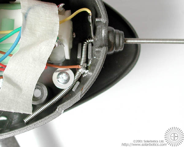
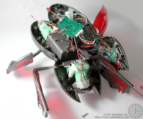
Let's start with a close-up of the rear bump sensor. According to the directions, this sensor can wake a "sleeping" B.I.O. Bug, or kick it into "overdrive", which is a double-time walking gait so it really scoots along. Notice the extra long spring they left in the interior? Makes you wonder if you could extend that sensor with little effort...
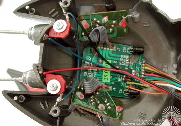
Here's a close-up of the 3 circuit boards that make up the head IR detector / emitter set, as well as detail of the front tactile sensors. I haven't had the time to analyse the data output of the IR circuitry, but it was easy to tell that the tactiles have a common ground wire with 2 signal leads running back to the main PCB.
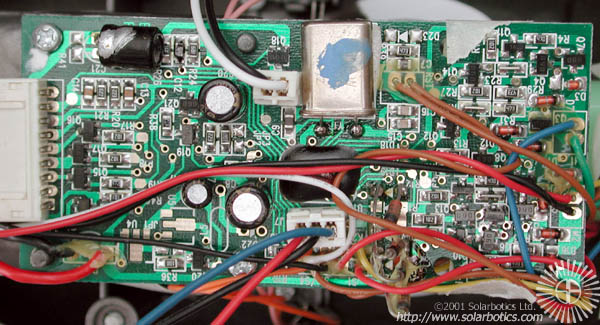
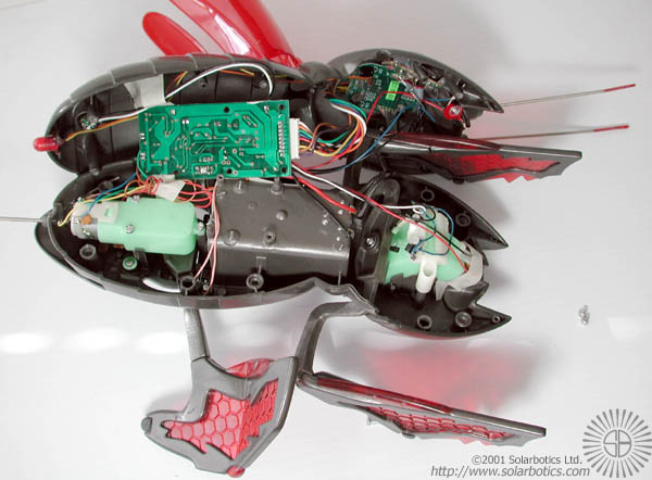
Here's the main "brain" PCB of the B.I.O. Bug. It is constructed using traditional "blob" technology (a.k.a. COB, Chip On Board) where the main brain IC is mounted on the PCB and covered with an epoxy blob. Inexpensive, robust, and hard to hack or reverse-engineer.
There's plug-in connectors for the IR head unit (the big one on the right side of the board), the speaker, and the forward tactile sensors. Unfortunately, the motor wires are soldered directly to the board on the right side, which is a minor nuisance for a B.I.O. Bug hacker.
Previous Page <--> Next Page